

Two sensors of the same model, on the same motor, can tell very different stories. One, bolted to the bearing housing near the load zone, picks up the faint high-frequency signature of a developing bearing defect weeks before anything else notices. The other, stuck to the fan cover a foot away, reports nothing unusual until the bearing is close to failing. The electronics are identical. What differs is where they sit and how they are attached.
Sensor placement gets less attention than algorithms, but it sets an upper limit on what any algorithm can do. A model cannot detect a signal that never reached the sensor. This guide explains how vibration, heat, sound and electrical signals travel from a fault to a measurement point, what that means for placement and mounting, and how to avoid the most common mistakes.
Signals travel, and they lose energy on the way
Most machine faults begin at a specific place: a spall on a bearing race, a cracked gear tooth, a loose rotor bar, a hot connection. The fault creates energy, as vibration, heat, sound or an electrical disturbance, and that energy has to travel through the structure of the machine to reach a sensor.
Every step on that path changes the signal. Vibration crosses metal, then a bolted joint, then perhaps a gasket or a layer of paint, then a thin sheet-metal cover. Each interface reflects and absorbs some energy, and high frequencies suffer most. Heat spreads and averages out as it moves through a housing. Sound in air is mixed with every other noise in the room. The further the sensor is from the fault, and the more interfaces between them, the weaker and more blurred the signal becomes.
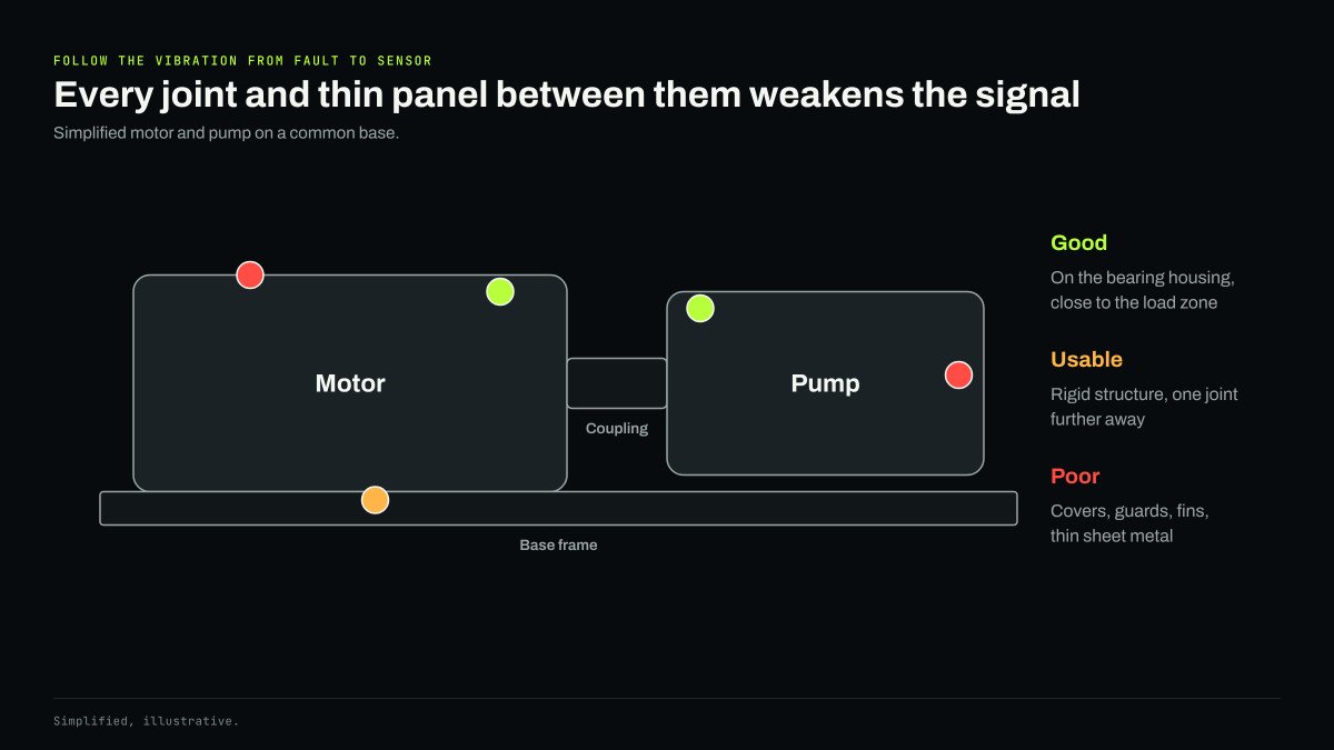
This matters most for early warning. The first signs of rolling element bearing damage are often at high frequencies, in the kilohertz range and above, as short impacts excite the structure. Those are precisely the frequencies that are lost first across joints and covers. By the time the fault has grown enough to show at lower frequencies that survive a poor path, much of the warning time is gone. We covered how these signatures develop in our explainer on vibration analysis.
Where to put a vibration sensor
The general guidance in ISO 20816-1 for measuring machine vibration focuses on the bearings, or the structure close to them, because that is where the forces from the rotor pass into the stationary machine. Practical placement follows from that.
- On the bearing housing. Mount as close as possible to each bearing, on solid metal that is part of the housing, not on a cover or a fin.
- In the load zone. On a horizontal machine, the radial load usually passes through the lower half of the bearing. A position that faces the load path receives the strongest impacts from defects.
- In the right direction. Radial horizontal measurements are often most sensitive to imbalance and looseness. Radial vertical measurements reflect gravity loading and some foundation problems. Axial measurements reveal misalignment and thrust bearing issues. Multi-axis sensors capture several directions from one position.
- On both ends. A motor and a pump each have bearings at the drive end and the non-drive end. Faults near the coupling show most clearly at the drive end positions.
- Away from resonant panels. Thin covers, guards and fan shrouds vibrate at their own natural frequencies and can amplify some signals while hiding others.
Compromises are common. Many machines have little space near the bearings, hot surfaces, or guards that cannot be removed. When the ideal spot is unavailable, the next best is rigid structure with as few joints as possible between the sensor and the bearing, and the compromise should be recorded so the data are interpreted with it in mind.
How the sensor is attached
The mounting method acts like a filter. A sensor joined rigidly to the surface moves with it across a wide frequency range. One held loosely or through a soft layer moves with it only at lower frequencies, and above some point the mounting itself resonates and distorts the measurement. ISO 5348, the international standard for the mechanical mounting of accelerometers, describes the common methods, including stud, adhesive, magnetic, quick-mount and probe mounting, and how each affects frequency response.
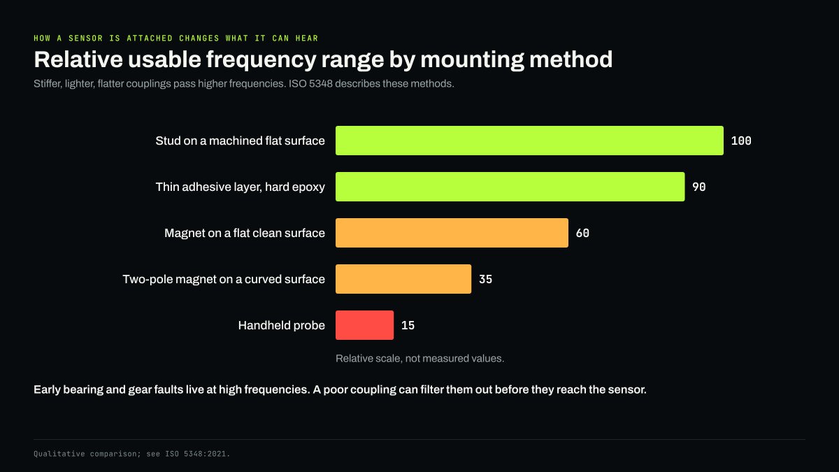
| Method | Strengths | Limits |
|---|---|---|
| Stud on a spot-faced surface | Widest frequency range; very repeatable | Needs drilling and tapping; permanent |
| Adhesive, thin and hard | Wide range without drilling | Surface preparation matters; removal can be difficult |
| Magnet on a flat, clean surface | Quick, movable, no machining | Narrower range; can shift under shock |
| Magnet on a curved surface | Fits round housings | Line contact reduces stiffness further |
| Handheld probe | Fast route-based checks | Low frequency only; varies with hand pressure |
Surface condition matters as much as method. Thick paint, rust, curvature and dirt all add compliance. A spot-faced or cleaned flat area, with paint removed down to metal, improves almost any mounting. Mounting torque for studs affects stiffness too, which is why manufacturers specify it.
For permanent monitoring, the attachment also has to last. A magnet that creeps across a housing over six months, or an adhesive that softens on a hot surface, changes the measurement slowly enough to look like a developing fault. Good installation practice records the mounting method and checks it periodically.
Thermal coupling
Temperature sensors face a related problem. A surface sensor measures the temperature of whatever it touches, and the bearing or winding of interest is often some distance inside. Heat flows outward and spreads as it goes, so the surface reading lags behind and understates the internal temperature.
That is not a reason to avoid surface measurement. It is a reason to place sensors on metal that is thermally close to the source, to keep the contact firm and clean, and to compare readings with ambient temperature and load rather than with a fixed limit. As we argued in thermal intelligence, temperature becomes useful when it is read in context. A bearing housing that runs 8 degrees warmer than last month at the same load and ambient is telling you something. A reading of 60 degrees on its own may not be.
Placement also guards against false readings. Anything sitting in the exhaust stream of a motor fan, or in direct sun on an outdoor pump, measures the air or the weather as much as the machine.
Sound and electrical signals
Acoustic sensing comes in two forms. Structure-borne sensing, through a contact sensor, behaves much like vibration and benefits from the same placement rules. Airborne sensing, through a microphone, can cover several components from one position but picks up every other source in the room, so distance to the machine and direction matter, and background noise has to be learned as part of normal behavior.
Electrical and magnetic signals have their own placement logic. Motor current analysis is usually done at the motor control center, not at the motor. Magnetic field sensing near a motor frame can reveal electrical asymmetries, but it is sensitive to position and to nearby cables. Variable speed drives and their cables can also inject electrical noise into any sensor nearby, so cable routing and grounding are part of placement too.
Placement and the device
A monitoring device that combines several kinds of sensing has to strike a balance. It needs firm mechanical contact for vibration, good thermal contact for temperature, a clear acoustic path, and a body compact enough to fit near the bearings on crowded machines.
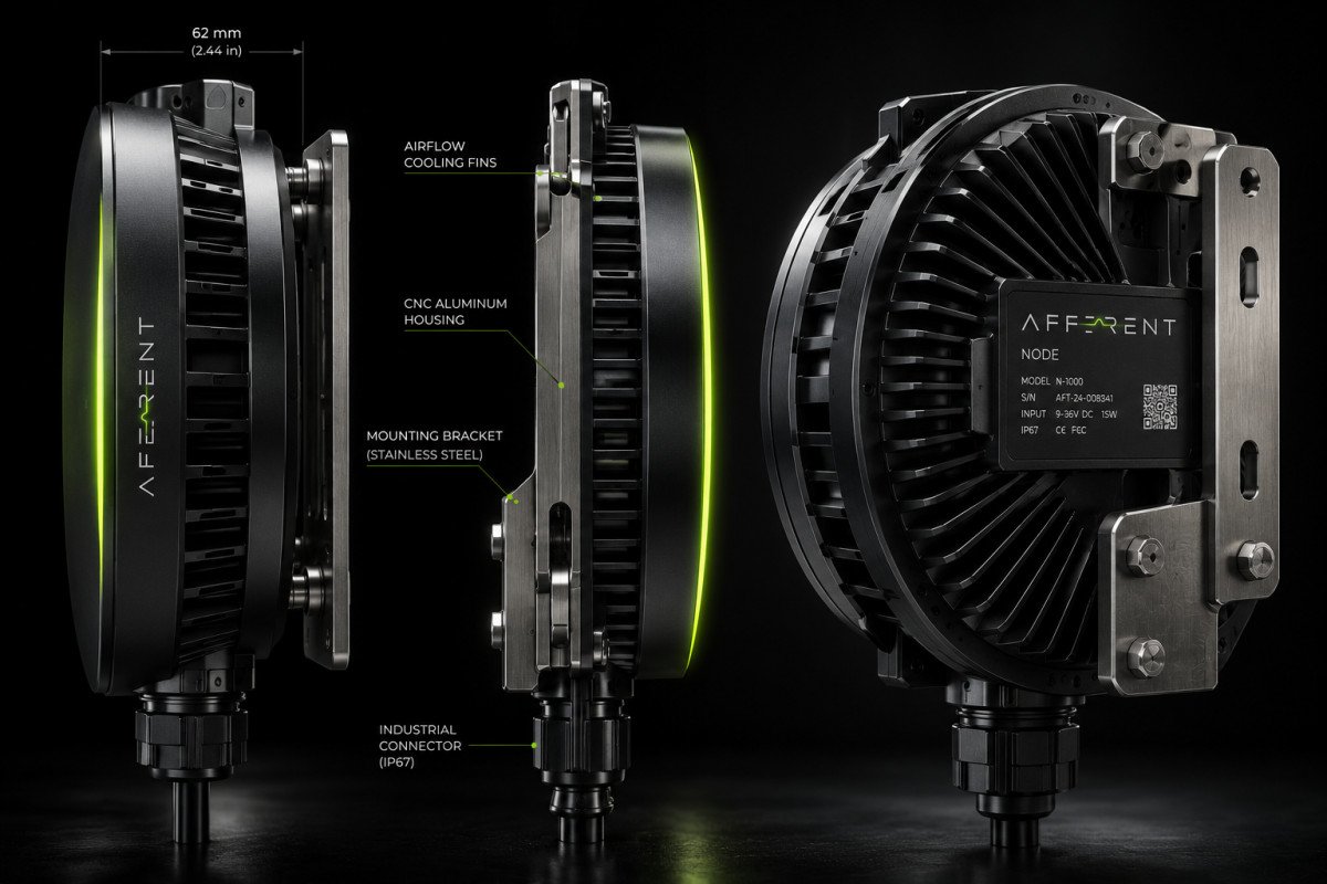
Those trade-offs shape how any multimodal device is designed and installed. They shape how we think about industrial sensor placement for NODE, and they are part of the case for reading several signals together rather than trusting any single measurement.
Mistakes that show up again and again
A few errors account for much of the poor data from field installations. Sensors end up on fan covers and terminal boxes because those surfaces are flat and easy to reach. Magnets go onto thick, curved, painted housings and are never checked again. Two sensors on the same machine are mounted in different directions, so their readings cannot be compared. And when a sensor is replaced, the new one goes on a few centimeters away from the old one, which quietly breaks the trend that months of history depended on.
A placement checklist
- Identify each bearing and the likely faults on the machine before choosing positions.
- Mount on solid metal of the bearing housing, in or near the load zone, never on covers or fins.
- Prepare the surface: flat, clean and down to metal where possible.
- Choose the stiffest mounting the site allows, and record what was used.
- Keep temperature sensors out of fan exhaust and direct sun, and read them against load and ambient.
- Route cables away from drive output cables and secure them so they cannot whip or pull.
- Photograph each installation so the next person mounts in exactly the same place.
Good placement does not make a monitoring program clever. It makes it possible.


