
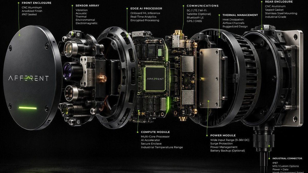
An industrial AI sensor looks simple from the outside: a sealed housing bolted to a machine, a cable, perhaps a status light. Inside, it has to do several hard things at once. It must capture faint physical signals in a hostile environment, analyze them with limited power and memory, keep working when the network fails, and stay secure for years on equipment that may sit at the heart of a critical facility.
This article walks through the architecture we are designing for NODE, function by function. NODE is in development. What follows describes the design intent and the reasoning behind each choice.
Five functions, one device
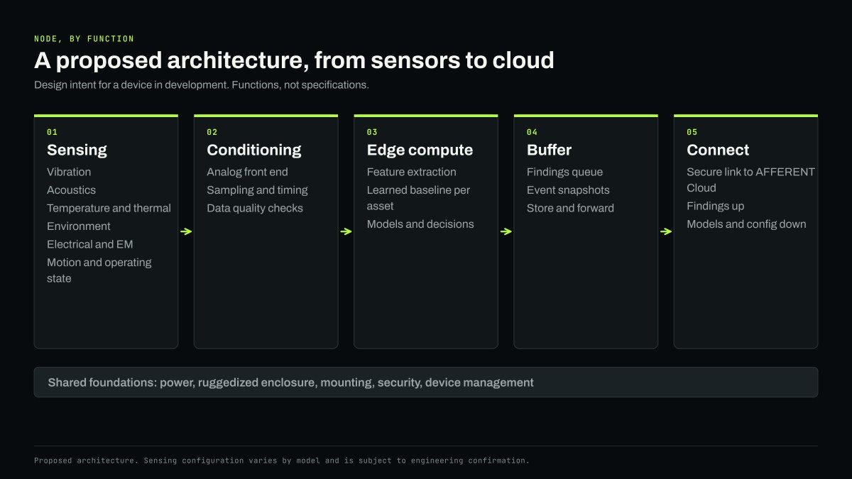
Most embedded condition-monitoring devices share a basic structure, and NODE is no exception. Signals are sensed, conditioned, analyzed, buffered and communicated. The design choices within each function are where products differ.
Sensing: several witnesses on one asset
The sensing modalities planned for the NODE family include vibration, acoustics, temperature and thermal signatures, environmental conditions such as ambient temperature and humidity, electromagnetic and electrical behavior, and movement and operating patterns. Not every model will carry every sensor. NODE Mini is intended for broad coverage of smaller assets, NODE Industrial for the motors, pumps, compressors and fans that plants depend on, and NODE Critical for assets such as transformers and generators whose failure is least acceptable.
The case for several modalities on one device is the one we set out in our article on sensor fusion. Each signal sees part of a machine's condition and each has its own sources of error. Measured together, on the same asset and against the same clock, they can confirm or rule out each other.
Placement is a design problem in its own right. A vibration sensor is only as good as its mechanical coupling to the machine; a loose or resonant mount can distort the signal it is meant to capture. Acoustic sensors need a path to the sound of interest without being swamped by the rest of the room. Thermal sensing needs a view of, or contact with, the surface that matters. Much of the industrial design work is about making correct placement easy for the person installing the device.
Conditioning: clean data or nothing
Between the sensors and the processor sits the analog front end: amplification, filtering and conversion from analog signals to digital samples. It is unglamorous and decisive. No model can recover information that was lost here, and errors introduced here look like machine behavior later.
Two requirements stand out. First, sampling has to be fast enough and clean enough for the faults of interest, which for bearings means capturing high-frequency content. Second, all channels need a shared, accurate time base, so that a change in vibration can be matched with a change in sound or temperature at the same moment. This stage is also where the device checks its own data quality, flagging a saturated channel, a loose mount or electrical interference as a measurement problem rather than passing it on as a machine problem.
A worked example shows why those requirements are strict. Take a motor running at 1,780 revolutions per minute, about 29.7 rotations per second, on a common 6205 deep groove ball bearing. In the Case Western Reserve University bearing data, the outer race defect frequency of that bearing is about 3.58 times shaft speed, so a crack in the outer race shows up near 106 Hz, with harmonics at 212 Hz, 318 Hz and beyond. The fault itself sits in a low band. The earliest evidence of it often does not. Each time a rolling element strikes the defect it excites resonances in the bearing housing, typically somewhere between 2 and 10 kHz, and envelope analysis recovers the 106 Hz pattern from those bursts. Capturing a 10 kHz resonance cleanly takes a sample rate of 25 kHz or more, plus an anti-aliasing filter that removes content above half that rate before conversion.
That choice sets the data volume. Three axes at 25,600 samples per second with 16-bit samples produce about 154 kilobytes per second, or roughly 13 gigabytes per day from a single asset. Few industrial networks would carry that from hundreds of machines, which is the practical case for the next stage.
Edge compute: interpretation beside the signal
NODE is built around edge intelligence. Analysis is intended to run on the device so that it can learn what normal looks like for the specific asset it is mounted on and recognize a departure from it. We described the stages of that process in how edge intelligence works: extracting features such as band energies and envelope spectra, comparing them with a learned baseline for each operating condition, and deciding whether a change is significant enough to report.
The constraints are familiar to anyone who has built embedded machine learning. Memory limits model size. Power and heat limit how often the full pipeline can run. Models have to be compact, efficient and, above all, explainable: a finding should carry the evidence behind it, such as which feature moved, by how much, and compared with what baseline.
Running analysis on the device is a choice with consequences. It reduces the data that has to leave the site by orders of magnitude, it keeps detection working through network outages, and it keeps raw waveforms on the device unless they are needed. It also means the device must be capable enough to do real work, which shapes the choice of processor, the thermal design and the power budget.
Buffer: memory for the moments that matter
A device that only kept its conclusions would make it impossible to check them. NODE is designed to keep a rolling buffer of recent raw data, so that when something notable happens, the waveform around the event can be saved and sent for an engineer or a better model to examine. It also queues findings and summaries locally when the network is unavailable, and sends them in order when the link returns, most important first.
The same arithmetic sizes the buffer. Ten seconds of raw three-axis data at the rate above is about 1.5 megabytes, enough to hold the waveform before and after an event. An hour is about 550 megabytes. The design question is not whether to keep everything, which no small device can, but which windows to keep: a short rolling record that is always available, plus longer captures triggered when a finding is raised or an engineer asks for one.
Connect: small messages up, improvements down
NODE is designed to communicate with AFFERENT Cloud, where findings from many devices are brought together into a view of a facility, a fleet or a portfolio of sites. The connection runs in both directions.
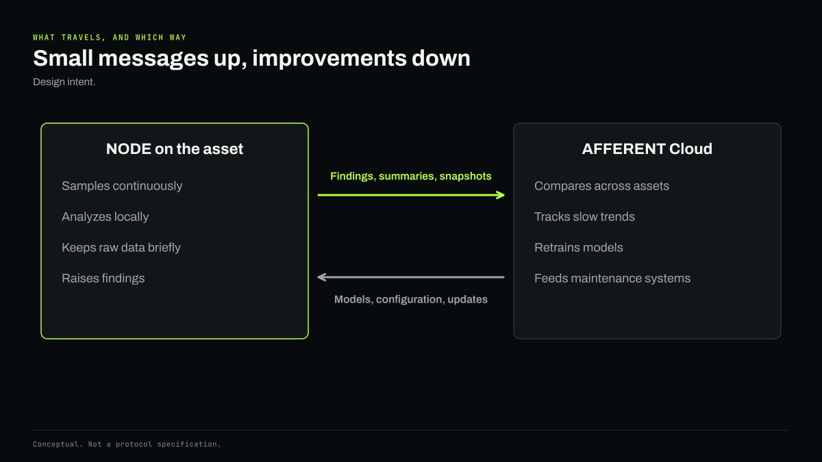
Findings, summaries and selected snapshots travel up. Improved models, configuration changes and firmware updates travel down. That two-way flow is what allows the system to improve over time: models learn from confirmed findings across many machines and are returned to the devices that need them.
Shared foundations
Several requirements cut across every function and are designed in from the start.
Security. A device attached to critical equipment must never become a way into the network it sits on. Guidance for operational technology, such as NIST SP 800-82 Revision 3 and the ISA/IEC 62443 series, sets expectations for segmentation, authentication and secure update. Our design principles follow the same lines: each device should be able to prove its identity, data is designed to be encrypted in transit and at rest, communication is intended to be initiated by the device so a facility need not open inbound access, and updates are designed to be verified before they are installed. Above all, NODE is designed to observe an asset, not operate it. A monitoring device that cannot command a machine cannot be used to command it. We do not display any security certification, and will do so only once one has been earned and can be verified.
Lifecycle. Devices will live in the field for years. They need secure, recoverable updates, a way to roll back a bad update, and a record of which model version produced which finding, so that every decision can be audited.
Ruggedization. Industrial surfaces are hot, the air carries dust, oil and moisture, everything vibrates, and drives fill the electrical environment with noise. The enclosure, mounting, connectors and electronics have to be designed for all of it. Harrison Brooks, our Co-Founder and CTO, leads this sensing layer: hardware, sensors, embedded firmware and ruggedization.
Power. Industrial sites offer different power options, and the power design affects how much analysis the device can afford to run continuously. The approach for each model will be confirmed through engineering and published with its specifications.
The architecture in brief
Taken together, the architecture comes down to a short list: several sensing modalities on one device, clean acquisition with a shared clock, interpretation at the edge, local memory for evidence, secure two-way connection, and a design built for the places machines actually live. More detail on each model will appear on the AFFERENT NODE architecture and product pages.


